Saturday, November 26, 2011

Back to the Furniture - Transforming Lumber thought Table Sketches to Finished Work!

After a long hiatus on furniture making, this summer was a chance to get back into the project that has been in my garage the longest, awaiting to be completed.
. 
The project of a Communion table for the Woodinville Church of Christ had started in thought a few years ago, but stalled for a time with a load of other activities taking my time.

100 BF rough cut Black Walnut
This project has become something special to work on as much of the tools and material used have a history.

The lumber comes from an elder 'George' in our church who has had this Black Walnut lumber drying in his garage for many years.  It was cut down in Washington maybe 30 years ago by his father. 
Roughly 200 board feet of Black Walnut was waiting for inspiration so as to be transformed into a table.  Shown to the left is about 100 BF measured and sorted.  It is ready for dimensioning.

I'll show more of that later, but needless to say this is rough cut 4/4 and 8/4 Black Walnut of a quality that I seldom see in such quantity in my humble shop.

George and I spent many days this summer cutting, sanding and scratching our heads trying to think carefully of what next.
  
Sketch Book of Table End
Personally I find it hard to create unless I can 'see' the end result. That is why I use sketch books (Yes and Google Sketchup) to capture ideas and passion.   I like to use the paperback size books as they are easy to sit with and hold while sketching.

A good mechanical pencil, a cup of coffee, a comfortable chair and the tools are in place to capture ideas as they come.

For this table I wanted to highlight the wood as much as possible.  The style I was looking for needed to be simple, not ornate, but capture some essence of its theological function.

The use of the pointed arches on each of the three side panels is what I decided upon as the theme catching element.  Three panels on each side to capture the essence of the Trinity.


Table End - Ready for final
There is much to post on this project but here is a glimpse of what is taking form.

The sides have been done very close to the sketch.  Design is a constant revisit of form and function.  The tapers where kept as the inverse taper.  But I opted not to have through tenons as it kept the look and work simpler.

This wood is far too nice to cover-up with standard finishes!

There will be no stain and poly urethane process here. It will be an oil finish. "George" likes the Danish oils as it pulls out the wood tone real nicely.


Much more to come....

Wednesday, June 22, 2011

Van de Graaff in the Garage

Sparks will fly!
Happiness is an excuse to build a Van de Graaff generator because your son needs one for a physics assignment. OK so he didn't need that big of one, but why not teach the next generation to dream and plan big.  If you are going to make an electrostatic discharge to impress your friends it had better be real long and snap real loud!    Ok here we go, this entry is a montage of our latest built in the shop project.

Let the Sparks Fly!
 The deal is garage science projects need to be done on a budget, and on time.  The project must teach something (skills in construction or science ) and it absolutely must be over-the-top fun!

A Van de Graaff (VDG) generator generates static electricity in large potentials. Generating 100kV is in itself cool. Discharging it to produce 3 to 4 inch sparks is way cool.  Since there is no current it is relatively safe - at least in the size we built.  NOTE there is already shop talk of VDG2 and how to make it better!

That's using your head!

There are many many sites on the Internet that show general plans for a VDG.  We took a look at a few and came up with our own ideas to fit tools available in our shop.  Most of the materials used are surplus items or low cost purchases from a local hardware store.  The domes used are stainless steel salad bowls we found at Fred Meyers.  Although they work the rim causes some unwanted discharge.  Very late in the build we found rimless bowls at our local Ikea store - hence the idea of VDG 2.
The tower is 4 inch PVC that is held in place with a PVC pipe-stand piece we found at Lowes.
Rubber belt cut from sheet shown with top pulley mount.
The belt material was the single most expensive purchase - but we wanted enough material in case things did not work out in the first attempt.  I found rubber sheet sold by the foot at Hardwick and Son's Hardware in the Seattle U district.  At first we thought joining the belt would require lacing.  It turns out the rubber glues very well with cyanoacrylates.  To join the edges we scarfed the rubber at 45 degrees.  A little glue on the bevel, press fit the edges, and clamping it down to hold in alignment and the belt was done.  Note our first belt was 2.5 inches wide but turned out to be too big.  We settled for a 2 inch wide belt in the end.  It was cut from 4 feet long rubber sheeting.

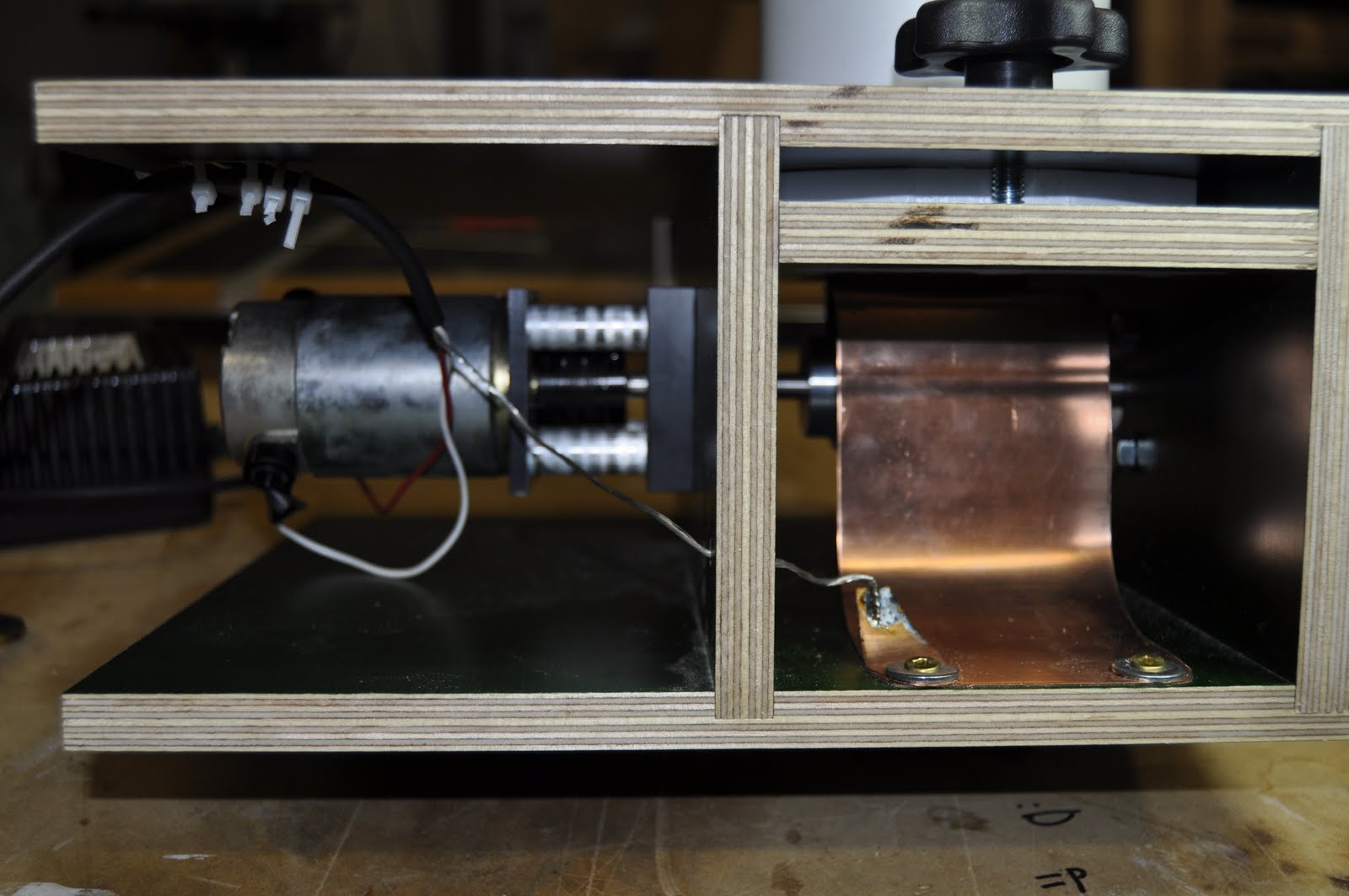
The static potential is generated by the belt carrying charge from a bottom (metal) pulley to a pulley (nylon) located on top of the PVC tower and inside the bowls (err domes).  A copper comb near the bottom pulley sprays charges onto the belt.  In our case this comb is electrically grounded.  Another comb on the top side transfers the charge from the belt to the dome.  By Faraday's law the charge should accumulate on the outside of the dome.  The picture below shows the mechanism used to hold the bowls to the tower and align the top pulley in place.  The position of the top comb can be seen just above the peak of the belt's travel.

Dome bottom with pulley and comb assembly

The top mechanism became quite involved but it works great.  Everything is built from plastic and nylon except for the copper combs.  Once assembled (with he belt through the pulley) the entire assembly rests on top of the PVC tower.  Notice that the charge is carried from the comb to the bottom bowl by the copper strap seen on the lower right. 


Making the top pulley bearing mount

Cutting hole in dome bottom


Bottom comb with grounding wire

Wood base, motor mount and bottom pulley
(obscured by the copper comb)


Center drilling the aluminum bottom pulley

Center drilling the top nylon pulley


Close up of plastic ring assembly used
to hold and align the bowls/pulley
   
Machining the rings to hold the
bottom bowl /top pulley to the PVC tower


More details to follow - stay posted!


Monday, May 30, 2011

Manipulating the Future

This project is a home-brew of a parallel manipulator robot known as a Delta-Robot. This robot has 3 degrees of freedom and allows for very fast positioning of it moving platform. The project started as an idea for learning\teaching kinematics. With too much on the go with other activities progress was idle for some time. Although the mechanical work is near done there is a load of software work now to make the robot useful.


The interesting feature of this robot is its design symmetry. There are relativley few different parts. The XYZ movement of the triangular platform (end effector) is accomplished via three angular joint mechanisms that are placed 120 degrees apart on the base.

Note the implementation shown is still missing the mount to hold it upside down from what is pictured.
The joint mechanisms are each controlled by a separate model airplane servo that pivots the fore arm. This arm is attached to a parallelogram seen as the parallel white rods in the photos. The parallelograms pivot on the fore-arm and the end effector. Again, three assemblies of the servo, fore-arm and parallelogram are placed at 120 degree angular spacing.


From the two photos shown next one can see the rather large range of motion the end effector can have with little change in the fore-arm's angular position.

The project is built with black lexan, while delrin and white fiber glass rods. Although it is not as light as it could be the implemention is sturdy and allows for a good deal of force.

The servos are controlled by a serial servo controller. (The small circuit board shown).

The end-effector platform can be seen below as the three-legged black lexan piece. The joints for the parallelograms are also made from black lexan. Some 8-32 nylon screws hold the pieces together.


More on all this later......


Saturday, November 13, 2010

Boxing Day

Having newly made tools just lie around on a bench or in a drawer simply isn't right. Here is a weekend fun project of resawing, box-jointing and making a home for a tool from a previous post.


That't right the words are cut on the CNC. I use DeskEngrave to make the G-Code for the working. It is a free-bee PC tool. Try it if yo want to make some quick signs or lettering.


Wednesday, September 8, 2010

Pinion Jigs and fly cutting

I think I said it earlier that model engineering and in particular clock making is the art of making tools to make tools that make parts. Although there has not been much shop time lately I did take some time at the end of the summer (2010) to build a pinion milling jig. The plans for this came from Model Engineer's Workshop #164. Not having large mild steel on hand I made it from aluminum.

The lesson here came from proper grinding of a fly cutting bit. Have a look at this great site for details on grinding a fly cutter bit. http://start-model-engineering.co.uk/begin-with-bogs/fly-cutting/
This site is an excellent resource and a good list of model engine projects.


Friday, October 2, 2009

Tesla Turbine

The Motivation to Build

Sometime multiple things need to come together to make things happen. Sometimes people need to come together to create the drive for things happen as well. The motivation for this project came about as a father-son lets-build-something-cool in the shop and spend less time in the 'virtual world' of video games. argh..sigh... Dad.... Perhaps motivated by my observation that my son's interests are different than mine, as mine were different from my father's, but realizing all are linked by a common drive for understanding. Or maybe it was just a nice distraction to build something in the shop while talking between generations.

The Project

This project is a high-speed turbine, based Nikola Telsa's idea, as implemented with plans found here:
www.instructables.com/id/Build-a-15%2c000-rpm-Tesla-Turbine-using-hard-drive-/


and also here:
www.blogger.com/www.phys.washington.edu/users/sbtroy/Tesla_Turbine/Tesla_Turbine.html

This project came about after a few things came together
(1) watching a PBS show on Nikola Tesla www.blogger.com/www.pbs.org/tesla/,
(2) a chance surfing-stumble across a related link on the DIY website www.instructables.com/, and
(3) a sudden thought on what to do with a bunch of old hard-drives piling up in the junk-bin.
The first cool part here was taking apart old hard drives. It is amazing the converstation you can have with teenagers when you are busy on a fun project. Needed was the aluminum platters contained in each drive. These serve as the smooth serviced disks that Tesla used in his turbine.


Cutting the Ventalation Slots in Platters
The Hard Drive platters serve as the turbine disks. However they require slots cut in them to allow for the air (fluid) to exit dear the center of rotation. Three arcs were cut with a 0.250" end mill. Rather than use a rotary table, the CNC milling was machine was given some quick GCode.


This is always fun to watch when the machine is cutting on its own. A simple clamping jig allowed for disks to the aligned on the table repeatedly. These disks are made of aluminum and cut fairly easily. The picture above shows the end result along with the needed spacer.


Cutting Ventalation slots in the housing
Ow this posting is skipping a lot of steps. Below is a video of the ventalation slots being CNC'd into the side of the housing. Cutting in plexi is real easy. Can't say I know the actual cutting RPM, trial and error gave a nice result. Going too fast melts everything.


Stacking the Disks on the arbor
Below you can see the arbor carrying the disk stack. This build used 8 disks separated by about 0.030"


More to come....

Wednesday, September 23, 2009

Round Table Affairs

This was a couple weekend project - ok - maybe a few evenings too once you include finish. I needed a table to put my coffee on when I sat in the sofa and this looked like a great design. This is a nice design that really calls for an Oak or Walnut construction but I had some Douglas Fir in the shop that was begging for existance as furniture.

The original plan is from Finewoodworking. Although not built completely to the drawings, it features the same slot mortises and tenons with a round top and shelf. You can find the plans and instuctions here. http://www.finewoodworking.com/projectsanddesign/projectsanddesignarticle.aspx?id=29314


Tools used include the table saw, jointer, planer, tenon jig, power mortising tool (oh you could hand cut those?), band saw and sanders of course. Sorry lathe - not this time.

I used one coat of sanding sealer and then three of shellac. The idea here was to get a nice but simple table into service as quick as possible.
Lots of fun to build in the workshop.


Tuesday, June 30, 2009

A light diversion

As a break from clock building and a chance to get at backlogged projects, I took a few weekends of shop hours to complete these sconces.
The backyard needed lights on the patio. In total the patio will need four, but this blog entry shows two under construction. This was a change from previous large scale furniture projects and thus required much less material. That's a welcome change on the pocket book.

This project is a modification of an Arts & Crafts Sconce found on Wood Store . net


I modified the back for a simpler project. The light socket was changed to use a low-voltage screw base lamp. The light diffuser is a frosted Mylar. The plan calls for Mica sheets, but to date I am all out of that material...The roof material is copper sheet. I pounded the copper against a hard board to give it the hand-hammered look.

The wood used is padauk. This is an interesting species to use due to its reddish/orange color (and dust!). I had two short planks of this lying around for some time. As they say all good things come to pass (through the table saw sooner or later!) http://www.woodmagazine.com/materials-guide/lumber/wood-species-3/padauk/

The design of the lantern is simple enough with a solid back and three identical sides. All are mitred to 45 degrees. The resulting four pieces are then glued together, some copper sheet metal work, add a frosted Mylar insert and voila - you have (most of) a sconce.


Hard to see in this daylight picture, but at night they look just grand!

Tuesday, May 12, 2009

Getting a Handle on Things

For many steps in making clock parts there is a good reason to turn the lathe by hand. Any type of threading is such a reason. Well after turning the chuck by hand for all the screw and stand-off threads needed for this project, I got tired. So I guess it is time for another tool.

This time I needed a hand crank so I could turn the lathe manually. An upcoming step in the clock barrel manufacturing will require screwcutting a 12 tpi "groove" in which the cable will wind. having worn out my hand turning the chuck manual for other screwcutting tasks, it seemed reasonable to build a hand-crank.


For a plan I use yet another from the following website. http://www.toolsandmods.com/ralph-patterson.html The design is Hand crank for 7x lathe (version 3).


The shank is made from 1.125 tool steel turned down on one end to 0.795 so as to fit in the lathe headstock spindle. It is drilled through for a 5 1/2 inch 3/8-16 bolt. The end of the shank is tapped to accept the 3/8-16 threads. The shank is then cut on a 30 degree diagonal. As the bolt is tightened the shank pieces slide diagonally to wedge themselves in the lathe spindle.
The arm is made from 0.250 aluminum cut to a key-hole shape. A square hole is cut in the larger end and fits over a matching square cut in the shank. Bending the s-shape took some prying in a vice.

The handle grip is a piece of oak that was turned to a comfortable fit in the hand. I used a 5/16 bolt to fasten it to the arm. I rubbed it with linseed oil as a preemptive strike of getting machine oil on it. Smells nice - looks nice.

The whole assembly fits into the lathe spindle as shown. The crank wedges in the spindle as the wedge-bolt is tightened.

The lathe can be easily turned by hand, both forwards and backwards, and makes a simpler job of manual screw cutting. Why didn't I build this first?

Saturday, April 4, 2009

The humble task of making cheese head screws

Yes you can buy screws - but if you are building a clock and are trying to learn the craft of home shop machining, what better activity than to make Cheese Head screws - from scratch. These screws are used to hold the clock plates to the stand-offs.


The making of the screws has a few steps that are somewhat time consuming but the results are worth the time. The experience of doing, making mistakes and learning is all found here. It is humbling to get it right despite being a simple item like a scew.

This task required a few steps and excersises a few skills; turning, threading, parting, and slitting.

(1) Parting and Turning The screws are made of 3/8 drill rod. The material is held in the three-jaw chuck and then faced. A parting tool is used to cut what will be the bottom of the head. This is about 11 mm in from the faced end and done to a depth that leaves 3 mm diameter on the stock. The faced end to the part is then turned down to 4 mm in diameter.


(2) Threading. The stock was turned to 4 mm in diameter and then threaded with 4 mm x 0.7 die (used in the tail-stock die holder). The intial parting in step 1 done to a 3 mm dia leaves a small area unthreaded next to the bottom of the head. Threading is all done with the lathe OFF and the chuck rotated by hand.


(3) Parting to size. The stock is again parted. This time the part forms the top of the head. The end result is a threaded screw with a nice flat (cheese) head. But - oops - it has no slot to make it useful.


(4) Slitting. The screw needs a slot. So over to the milling machine to use a 1/16th slitting saw and a jig to do this. The jig is simply a piece of alumimum tapped for the 4 mm x 0.7 thread. The screw blank is hand threaded on and the saw is centered on the screw head diameter.


One lesson learned here by trial and big error is the cutting speed of the tool needs to be slow. The saw is 2 1/2 inches in diameter. My first attempt was at a real highspeed which lead to disaster. The HSS slitting tool instanly went dull. The corrected process to cut the slot (under CNC control) was to set the head RPM low - maybe 300-500 (sorry no tach yet) and a feed of 2 inches per minute. A first cut of 0.01 inches was done to establish the slot. Then two more cuts at 0.035 and then 0.070 depth were done. It sounds horrible when cutting but the results are great.


With CNC control on the mill this was the time to sip Saturday morning coffee while the machine cuts away - at least after the sequence of G-Codes was entered. Using EMC2 in MDI mode (manual command entry) it was simple work to enter a few lines of G-Code to repeat the slitting operation at the depth passes mentioned. Now if I only had the lathe CNC'd then the enter screw making process would be much much quicker.....