It is Dec 26th 2021 at the time of this post. Boxing Day. It has been a very long time since my last post. It feels like an even longer time since the Covid 19 pandemic started. All is well here as I wish it is with you out there.
Since my last posting, I have ventured into G Scale garden trains. I must say this is an 'all-up' hobby that can use and consume all of one's skills and interests. Further it is great motivation to get back into blogging!
Here is a bit of a 'catch-up' on activities. Yes, I did say it was a G-Scale garden train and yes this is my garage, not my garden. But I also said it is December - and it is raining - and my garage is warmer. nuff-said.

Here is a bit of a 'catch-up' on activities. Yes, I did say it was a G-Scale garden train and yes this is my garage, not my garden. But I also said it is December - and it is raining - and my garage is warmer.
I have built a test track in sections that allow for modular assembly and disassembly. So far it is a basic loop. Straight sections are just over 4 feet long and use two sections of LGB 10600 Straight Track, which are each 23-5/8" long.
The 90 degree curved sections are made with three pieces of LGB 11000 Curved Track, R1, 30 Degree.
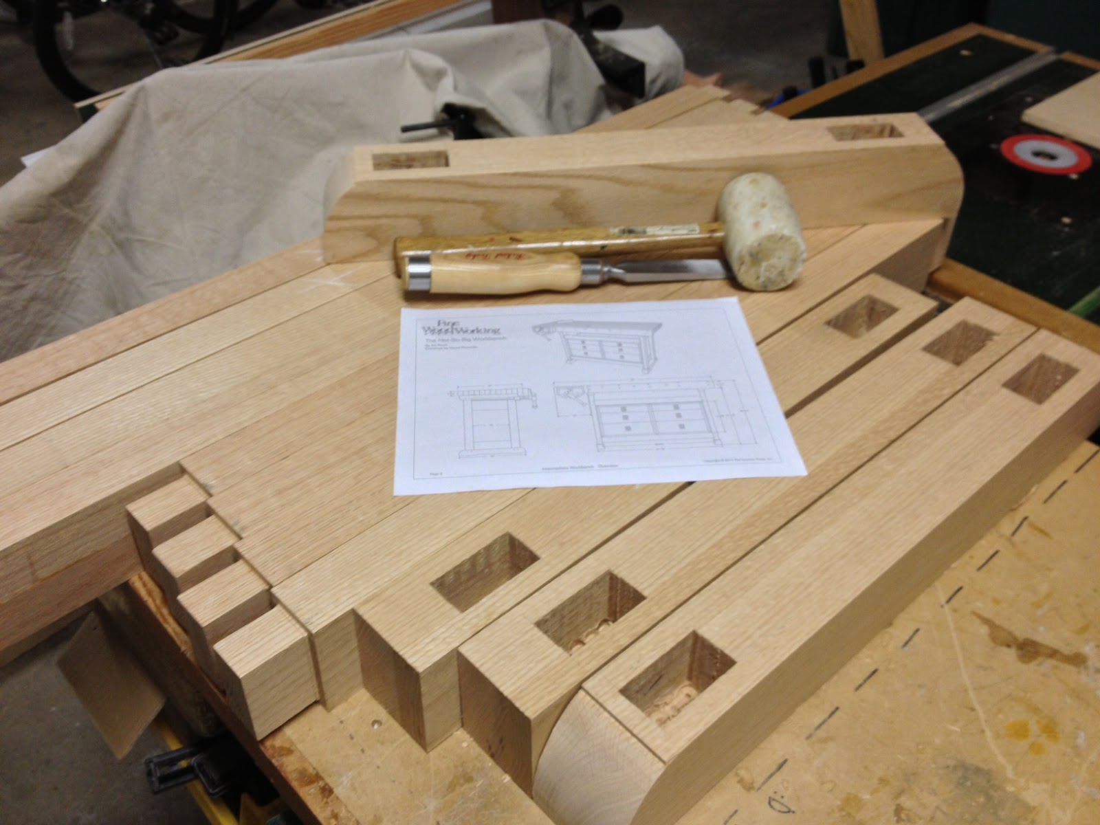
Each section stands on a wooden support which simulates a trestle bent.
The wood sections are aligned with the dowel and hole setup as shown. When the sections come together I use a short track segment to join the rails. That way when apart the attached track does not over-hang the wood. The shorts are LGB 10080 Straight Track, which are 3-1/4" long.

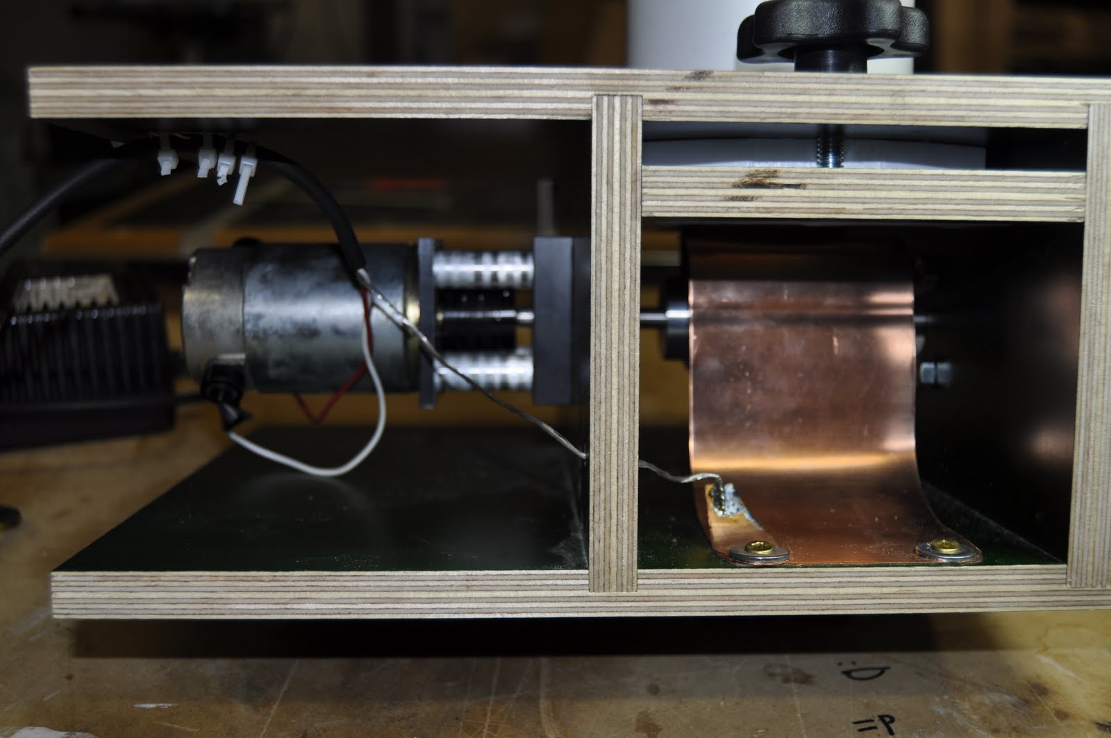
Power to the track comes from a DIY controller based on the CommandStation-EX project using the open-source software DCC++EX . Look here for details. This is a very well done open-source project.. The hardware is based on an Arduino MEGA and two high current motor controllers boards. One Motor controller powers the Main track, the other is available for the Program track. I run my rails on +24V and I can deliver over 10 amps to the track if need be.
Digital Command Control or DCC is the technology used to send power and commands to the locomotives. It has loads of capabilities. If you are interested the actual specifications for DCC are controlled by the National Model Railroad Association and are located here.
The following pictures show stages of the command station build.

Presently I use a web based Throttle called exWebThrottle to run the Loco. This program is a app that runs on Chrome and communicates the control station. The app allows for controlling the speed and functions on the Loco.

At the moment I have only one Loco on DCC. I accomplished that in a two-decoder method. I have an off-the-shelf DigiTraxx decoder running the motor and lights. For the horn, I have an Arduino and an SD card MP3 player 'listening' for the loco's addressed horn command. I can load multiple sounds on the SD card for other commands like 'Bell'.

Alright then, you can see I am deep into the electronics of DCC. My next project is a current detector for track occupancy. This will allow the command station to know where a loco is on the track. Further I am also looking into LCC which is the track control protocol for controlling lights, switches and other items. Details on LCC can be found here.
Alright then, you can see I am deep into the electronics of DCC. My next project is a current detector for track occupancy. This will allow the command station to know where a loco is on the track. Further I am also looking into LCC which is the track control protocol for controlling lights, switches and other items. Details on LCC can be found here.
Clearly more posts to come


 From the two photos shown next one can see the rather large range of motion the end effector can have with little change in the fore-arm's angular position.


